

WCL’26: Robust and Secure Communication with Bending Beams
Published:
At the end of 2024, I heard at Globecom in South Africa that some researchers had recently been working on bending beams with promising results. Related works had already appeared in Nature Communications1 and Communications Engineering2, attracting considerable attention. I did not dive into the technical details at the time; by the time I caught up, several papers had already been published, so I decided to modestly follow this trend.
This paper has been accepted by IEEE Wireless Communications Letters and is freely available on arXiv. Below is a brief introduction to the core ideas and methods.
Introduction
Honestly, finding an application scenario for bending beams is challenging. In modern beamforming, ZF and EVD are common approaches: by applying them to the channel matrix, the beam can be focused at the desired user location while suppressing interference and improving spectral efficiency. In recent mmWave and even THz systems, hybrid analog-digital architectures are widely used because high-frequency components are costly and power-hungry; the analog stage performs beam alignment and the digital stage removes approximation errors.
Under this conventional mindset, the shape of the beam does not seem to matter much. A beam shape that satisfies various requirements is almost certainly not the optimal solution of an optimization problem, and once the problem is formulated to be solvable by optimization, the optimized result is usually better regardless of the shape3.
After careful consideration, we adopted the physical-layer security scenario, which can effectively exploit beam shape. Because most bending beams have a radiation pattern that is significantly weaker on one side than the other, we leverage this property together with the curved shape to enhance transmission security.
Motivation
Near-field beamfocusing exploits the large aperture of XL-MIMO to concentrate energy at a specific location, thereby reducing the received signal strength at eavesdroppers in physical-layer security communications. However, in practice the eavesdropper’s location estimate is often inaccurate; even a small localization error can shift the focal point and severely degrade the secrecy rate.
Existing robust designs suffer from two main limitations:
- Most assume perfect eavesdropper CSI or rely on iterative optimization, which entails high complexity and is unsuitable for XL-MIMO systems.
- Near-field CSI uncertainty mainly stems from localization error rather than channel estimation error, so conventional far-field robust optimization methods (e.g., relaxation plus S-procedure) cannot be directly applied.
To address this, we propose a physics-inspired robust beamforming scheme based on the electromagnetic caustic (EM caustic) effect. By designing curved caustic beam trajectories that bypass the potential eavesdropping region, we achieve secure communication without iterative optimization.
System Model
Consider a near-field secure communication scenario where the BS is equipped with $M$ passive metasurface elements4 serving a single-antenna legitimate user (UE). An eavesdropper is also located in the near-field region of the BS.
We adopt the spherical-wave model for the near-field channel:
Because the eavesdropper does not cooperate in localization, its position is modeled as \(\mathbf{r}_{\rm E}=\hat{\mathbf{r} }_{\rm E}+\Delta\mathbf{r}\), where the localization error \(\Delta\mathbf{r}\) is constrained within a circular region \(\Omega_\varepsilon\) of radius \(\varepsilon\). We use a passive metasurface for analog beamforming, so the optimization variable is the phase-shift vector \({\bf f}\) subject to the constant-modulus constraint \(\vert f_m\vert = 1\).
The design objective is to maximize the worst-case secrecy rate over the eavesdropping region:
Phase Gradient and Beam Steering
The core idea of this paper is to control the phase gradient over the array to steer the emission direction of the EM wave. Below is a relatively accessible derivation; readers who prefer the conclusions may skip to the end of this section.
Consider a monochromatic EM wave $U(x,y)$ satisfying the Helmholtz equation. Let the trial solution be
Substituting into the Helmholtz equation gives
Rearranging,
Under the high-frequency (large wavenumber \(\kappa = 2\pi/\lambda\)) approximation, we obtain the Eikonal equation:
This means the gradient of the distance function $D(x,y)$ has unit length. Since the gradient of the distance function is always perpendicular to the wavefront, controlling the $x$-component of the phase gradient on the transmit aperture allows us to control the emission direction of the EM wave at each aperture position. Specifically, for a desired emission angle $\theta$:
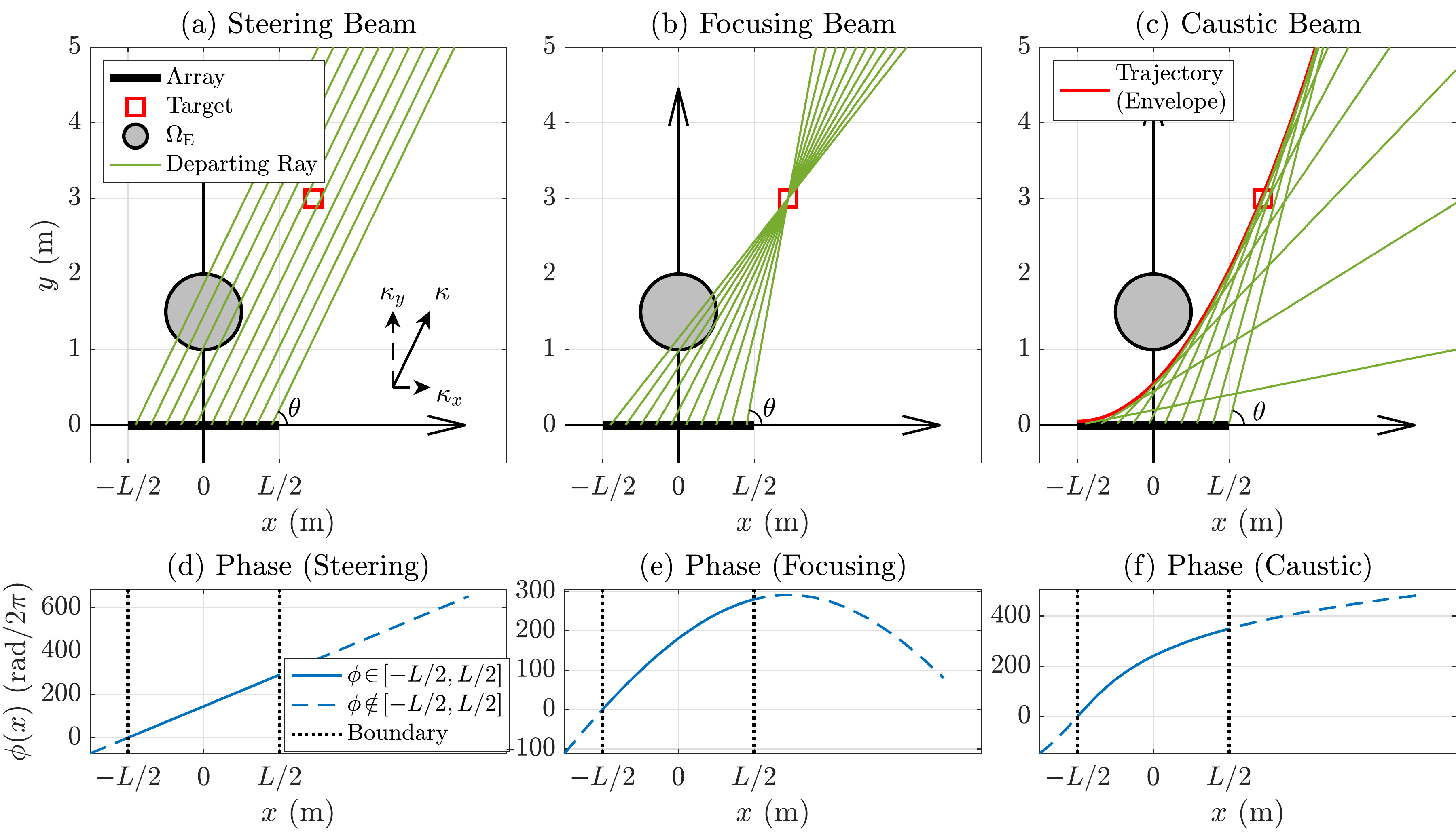
This relation is essentially the generalized Snell’s law5. From it we can derive different beamforming schemes:
- Beam steering: fix the emission angle \(\theta\); the phase distribution is linear, \(\phi(x) = \kappa\cos\theta \cdot x + C\).
- Beam focusing: the emission angle varies with $x$ so that all rays converge at the UE location; \(\phi(x) = -\kappa\Vert {\bf r}_{\rm UE} - (x,0) \Vert + C\).
- Arbitrary beam trajectory: solve the differential equation directly. For example, for a parabolic trajectory, if $f(x)=(x/a)^2$, solving$$ \left.\frac{\partial \phi(x)}{\partial x}\right\vert_{x=x_\xi} =\kappa\cos\theta = \frac{\kappa}{\sqrt{1\!+\!\left( f^\prime(\xi) \right)^2}}, $$
yields
$$ \phi_{\rm Quad}(x) = \frac{\kappa a^2}{4}{\rm asinh}\left( \frac{4x}{a^2} \right). $$
Caustic Beam Trajectory Design
With the above beam-design tools, we can design a beam that bypasses the eavesdropping region.
Piecewise Trajectory Design
To balance security and energy efficiency, we partition the BS array into a caustic subarray and a focusing subarray:
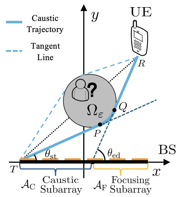
- Caustic subarray \(\mathcal{A}_{\rm C}\): elements whose line-of-sight path is blocked by the eavesdropping region emit beams along a caustic trajectory that circumvents \(\Omega_\varepsilon\).
- Focusing subarray \(\mathcal{A}_{\rm F}\): elements whose line-of-sight path does not pass through the eavesdropping region focus energy directly at the UE.
The piecewise caustic trajectory consists of three segments: tangent segment \(\overline{TP}\) + circular arc \(\widehat{PQ}\) + tangent segment \(\overline{QR}\).
Closed-Form Phase Distribution
For the caustic subarray, solving with the emission angle \(\theta\) as a parameter yields the closed-form phase distribution:
where
For the focusing subarray, the phase distribution is the classical focusing phase. The overall phase distribution is a piecewise function with continuity enforced.
Notably, this closed-form solution requires no iterative optimization and can be computed directly from geometric parameters.
Simulation Results
Beam Visualization
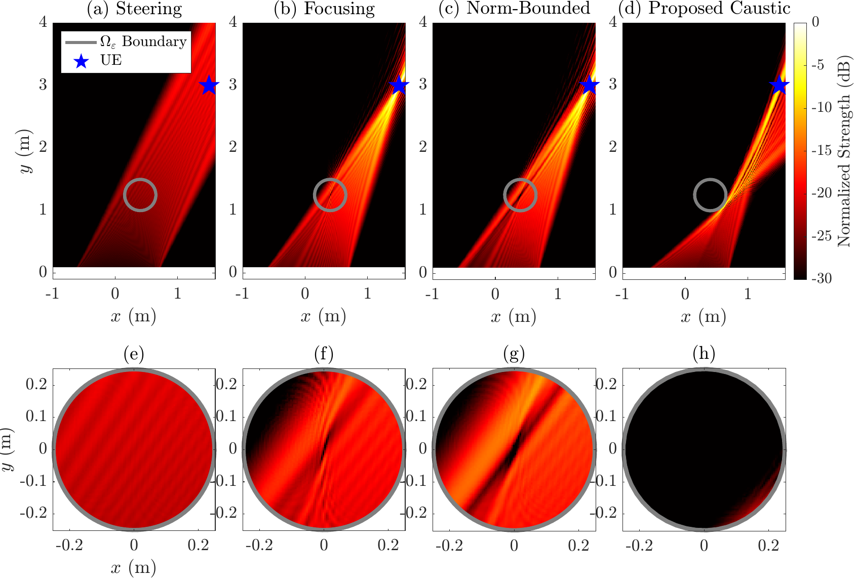
The figure above shows the normalized radiation intensity under different phase designs. It can be seen that:
- The beam-steering scheme (a) leaks significant energy into the eavesdropping region.
- The baseline schemes (b)(c) can suppress leakage only over a small part of the eavesdropping region.
- The proposed caustic beam (d) successfully bypasses the entire eavesdropping region, achieving near-perfectly secure communication.
Secrecy Rate
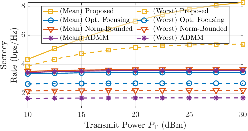
Across different transmit powers, the proposed scheme significantly outperforms the baselines in both average and worst-case secrecy rate. Especially in the high-SNR regime, conventional schemes saturate while the caustic beam scheme keeps increasing because it effectively suppresses energy leakage into the eavesdropping region.
Computational Complexity
For $M=256$, the execution time of the proposed scheme is only about \(9.64\times 10^{-4}\) seconds, far below the baselines (Norm-Bounded: \(27.4\) s, ADMM: \(0.104\) s), and the time cost grows only slightly with the number of elements, demonstrating good scalability.
Citation
@ARTICLE{11505880,
  author={Liu, Shicong and Yu, Xianghao and Schober, Robert},
  journal={IEEE Wireless Commun. Lett.},
  title={Robust and Secure Near-Field Communication via Curved Caustic Beams},
  year={2026},
  volume={15},
  number={},
  pages={3069-3073},
  keywords={Antennas;Apertures;Feeds;Antennas and propagation;Phased arrays;Radio broadcasting;Frequency modulation;Phase noise;Phase shifters;System-on-chip;Caustic;near field;robust design;secrecy rate;secure communication},
  doi={10.1109/LWC.2026.3690036}}
S. Liu, X. Yu and R. Schober, "Robust and Secure Near-Field Communication via Curved Caustic Beams," IEEE Wireless Commun. Lett., vol. 15, pp. 3069-3073, 2026.
To Be Continued
Further Reading
Chen, H., Kludze, A. & Ghasempour, Y. A physics-informed Airy beam learning framework for blockage avoidance in sub-terahertz wireless networks. Nat Commun 16, 7387 (2025) ↩
Guerboukha, H., Zhao, B., Fang, Z. et al. Curving THz wireless data links around obstacles. Commun Eng 3, 58 (2024). ↩
Although I am not familiar with optimization theory, I have heard this viewpoint mentioned at multiple venues such as the EI Conference and ICC’26. This is only a quotation. ↩
A metasurface is a low-cost, high-precision phase-modulation solution; the proposed scheme can also be implemented with other hardware. ↩
N. Yu, P. Genevet, M. A. Kats, F. Aieta, J.-P. Tetienne, F. Capasso, and Z. Gaburro, “Light Propagation with Phase Discontinuities: Generalized Laws of Reflection and Refraction,” Science, vol. 334, no. 6054, pp. 333-337, 2011. ↩